As I mentioned earlier, I needed to add rotary encoders on the wheels in order to measure their angular velocities. This was required to enable using a closed loop control algorithm that could keep the robot driving straight with constant velocity.
Rotary encoders are available as off-the-shelf components, complete with encoder disks and sensor modules, but they are somewhat costly considering their simplicity. Many of them are also not suitable for my purposes because there is not much room to mount stuff between the wheel and the servo assembly in SHORT-E.
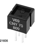
I did some research and decided that I would need photoreflectors. Hamamatsu P306201 was used in Mobile Robots - Inspiration to Implementation, but neither it or its newer replacement, P5587, were available anymore, at least not on this side of the Atlantic Ocean. I then came across Vishay Semiconductors CNY70 that seemed promising. I ordered some online from Elfa. They cost 0.79€ each in a batch of ten.

A photoreflector combines an IR-emitting diode with a phototransistor and is able to sense whether the IR light it emits is reflected back or not. If one is mounted near a spinning wheel that has a striped black-white pattern, an appropriate circuit will produce a logic-level pulse stream whose frequency is directly proportional to the angular velocity of the wheel.
I printed two copies of a 24 stripe pattern I found on the web, cut them to size and glued them to the inside surfaces of SHORT-E's wheels. I then took two CNY70s, soldered wires to each of their pins, and completed two copies of the following circuit on SHORT-E's breadboard:

Note: The orientation of the CNY70 component in the diagram is such that the markings ("V69 CNY70" etc.) are on the right.
This circuit produces output voltages that are close enough to +0V and +5V to pass for logic-level signals. 200Ohms and 10kOhms were the only resistor values I had in my component box, and they probably aren't the absolute best choices, but they seem to work well enough. You could try replacing the 10k with something a bit larger to get closer to +5V when there is white stripe in front of the CNY70 (I now get around +4V).
The CNY70s need to be mounted as close to the striped wheel surfaces as possible, I mean preferably less than half a millimeter according to the datasheet, although it doesn't seem to be too picky about the distance in real life.
The outputs of each circuit (see image above) I connected to pins 2 and 3 on my Arduino. I specifically selected these pins because they can trigger external interrupts. I then simply wrote interrupt handlers that increment pulse counters on each change of the signal, i.e. in setup() I added
pinMode(encoderLeftPin, INPUT);
attachInterrupt(0, doEncoderLeft, CHANGE);
pinMode(encoderRightPin, INPUT);
attachInterrupt(1, doEncoderRight, CHANGE);
Here encoderLeftPin and encoderRightPin are just names that correspond to 2 and 3, i.e. the Arduino I/O pin numbers for external interrupts 0 and 1. Functions doEncoderLeft() and doEncoderRight() simply just increment integer counters.
The code I described above just counts the pulses but does not affect control yet. In addition I implemented a PID controller and spent a few hours tweaking its parameters to get SHORT-E behaving nicely. PID controllers are textbook material and also the Wikipedia article I just linked to contains a nice pseudocode description as well as discussion on what the different parameters do. Therefore I think I won't go into the details here.
No comments:
Post a Comment